MRF5P20180HR6
3
RF Device Data
Freescale Semiconductor
Z11, Z12 0.341″
x 0.945
″
Microstrip
Z13, Z14 0.035″
x 0.913
″
Microstrip
Z15, Z16 0.581″
x 0.823
″
Microstrip
Z17, Z18 0.059″
x 1.057
″
Microstrip
Z19, Z20 0.081″
x 0.046
″
Microstrip
Z21, Z22 0.081″
x 0.126
″
Microstrip
Z25 0.081″
x 0.793
″
Microstrip
PCB Taconic TLX8-0300, 0.030″, εr
= 2.55
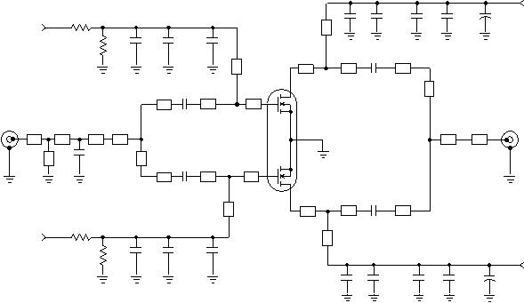
Figure 1. MRF5P20180HR6 Test Circuit Schematic
Z1 0.081″
x 1.126
″
Microstrip
Z2 0.079″
x 0.138
″
Microstrip
Z3 0.081″
x 0.091
″
Microstrip
Z4 0.081″
x 0.117
″
Microstrip
Z5, Z24 0.134″
x 0.874
″
Microstrip
Z6, Z23 0.081″
x 2.269
″
Microstrip
Z7, Z8 0.081″
x 0.118
″
Microstrip
Z9, Z10 0.081″
x 0.079
″
Microstrip
R1
R2
+
C14
C10
C8
Z13
Z1 Z3
RF
INPUT
C2
Z7 Z9
C3
Z8 Z10 Z12
Z14
Z17
Z18
C6
C12
+
C17
+
C20
+
C16
VSUPPLY
C7
C13
+
C19
+C21
+
C18
VSUPPLY
C4
Z15
Z19 Z21
C5
Z16 Z20 Z22
Z24
Z25
RF
OUTPUT
DUT
VBIAS
Z23
Z11
Z4 Z5
Z6
C1
Z2
R3
R4
+
C15
C11
VBIAS
C9
Table 5. MRF5P20180HR6 Test Circuit Component Designations and Values
Part
Description
Part Number
Manufacturer
C1
1.8 pF 100B Chip Capacitor
100B1R8BW
ATC
C2, C3, C4, C5, C6, C7
10 pF 100B Chip Capacitors
100B100GW
ATC
C8, C9
6.8 pF 100B Chip Capacitors
100B6R8CW
ATC
C10, C11, C12, C13
10 nF 200B Chip Capacitors
200B103MW
ATC
C14, C15, C16, C17, C18, C19
22 μF, 35 V Tantalum Capacitors
TAJE226M035
AVX
C20, C21
220 μF, 63 V Electrolytic Capacitors
13668221
Philips
R1, R2, R3, R4
10 k
Chip Resistors (1206)


发布紧急采购,3分钟左右您将得到回复。
相关PDF资料
MRF5P21045NR1
MOSFET RF N-CH TO-270-4
MRF5P21180HR6
MOSFET RF N-CHAN 28V 38W NI-1230
MRF5P21240HR6
MOSFET RF N-CHAN 28V 52W NI-1230
MRF5S19060MR1
MOSFET RF N-CH 28V 12W TO-270-4
MRF5S19060NBR1
MOSFET N-CH 12W 28V TO-272-4
MRF5S19090HSR5
MOSFET RF N-CHAN 28V 18W NI-780S
MRF5S19100HSR5
MOSFET RF N-CHAN 28V 22W NI-780S
MRF5S19130HSR5
MOSFET RF N-CHAN 28V 26W NI-880S
相关代理商/技术参数
MRF5P20180HR6_06
制造商:FREESCALE 制造商全称:Freescale Semiconductor, Inc 功能描述:RF Power Field Effect Transistor N-Channel Enhancement-Mode Lateral MOSFET
MRF5P20180R6
制造商:MOTOROLA 制造商全称:Motorola, Inc 功能描述:RF POWER FIELD EFFECT TRANSISTOR
MRF5P21045NR1
功能描述:射频MOSFET电源晶体管 HV5 2170MHZ 10W TO270WB4 RoHS:否 制造商:Freescale Semiconductor 配置:Single 晶体管极性: 频率:1800 MHz to 2000 MHz 增益:27 dB 输出功率:100 W 汲极/源极击穿电压: 漏极连续电流: 闸/源击穿电压: 最大工作温度: 封装 / 箱体:NI-780-4 封装:Tray
MRF5P21180
制造商:FREESCALE 制造商全称:Freescale Semiconductor, Inc 功能描述:RF Power Field Effect Transistor
MRF5P21180HR5
功能描述:射频MOSFET电源晶体管 HV5 38W WCDMA NI1230H RoHS:否 制造商:Freescale Semiconductor 配置:Single 晶体管极性: 频率:1800 MHz to 2000 MHz 增益:27 dB 输出功率:100 W 汲极/源极击穿电压: 漏极连续电流: 闸/源击穿电压: 最大工作温度: 封装 / 箱体:NI-780-4 封装:Tray
MRF5P21180HR6
功能描述:射频MOSFET电源晶体管 HV5 38W WCDMA NI1230H RoHS:否 制造商:Freescale Semiconductor 配置:Single 晶体管极性: 频率:1800 MHz to 2000 MHz 增益:27 dB 输出功率:100 W 汲极/源极击穿电压: 漏极连续电流: 闸/源击穿电压: 最大工作温度: 封装 / 箱体:NI-780-4 封装:Tray
MRF5P21180HR6_08
制造商:FREESCALE 制造商全称:Freescale Semiconductor, Inc 功能描述:RF Power Field Effect Transistor
MRF5P21180R6
制造商:MOTOROLA 制造商全称:Motorola, Inc 功能描述:RF Power Field Effect Transistor
